- 您现在的位置:买卖IC网 > Sheet目录264 > YC122-JR-0715RL (Yageo)RES ARRAY 15 OHM 2 RES 0404
�� �
�
�Product� specification�
�5�
�Chip� Resistor� Surface� Mount�
�YC/TC�
�SERIES�
�122� (RoHS� Compliant)�
�8�
�ELECTRICAL CHARACTERISTICS�
�Table� 2�
�FOOTPRINT AND SOLDERING�
�PROFILES�
�CHARACTERISTICS�
�Operating� Temperature� Range�
�Rated� Power�
�YC122� TC122�
�–55� °C� to� +125� °C� –55� °C� to� +125� °C�
�1/16� W� 1/16� W�
�For� recommended� footprint� and�
�soldering� profiles,� please� refer� to�
�data� sheet� “Chip� resistors�
�mounting� ”.�
�Maximum� Working� Voltage�
�Maximum� Overload� Voltage�
�Dielectric� Withstanding� Voltage�
�5%� (E24)�
�50� V�
�100� V�
�100� V�
�1� ?� to� 1� M� ?�
�50� V�
�100� V�
�100� V�
�10� ?� to� 1� M� ?�
�Resistance� Range�
�1%� (E24/E96)�
�10� ?� to� 1� M� ?�
�Jumper� <� 50� m� ?�
�10� ?� to� 1� M� ?�
�Jumper� <� 50� m� ?�
�Temperature� Coefficient�
�1� ?� ≤� R� <� 10� ?� ±250� ppm/°C�
�10� ?� ≤� R� ≤� 1� M� ?� ±200� ppm/°C�
�±200� ppm/°C�
�Jumper� Criteria�
�Rated� Current�
�Maximum� Current�
�0.5� A�
�1.0� A�
�1.0� A�
�1.5� A�
�PACKING STYLE AND PACKAGING QUANTITY�
�Table� 3� Packing� style� and� packaging� quantity�
�PRODUCT� TYPE�
�YC/TC122�
�PACKING� STYLE�
�Paper� Taping� Reel� (R)�
�REEL� DIMENSION�
�7"� (178� mm)�
�13"� (330� mm)�
�QUANTITY� PER� REEL�
�10,000� units�
�50,000� units�
�NOTE�
�1.� For� paper� tape� and� reel� specification/dimensions,� please� refer� to� data� sheet� “Chip� resistors� packing”.�
�FUNCTIONAL DESCRIPTION�
�P� O� W� E� R� R� A� T� I� N� G�
�YC/TC� 122� rated� power� at� 70� °C� is� 1/16� W�
�R� ATED� VOLTAGE�
�The� DC� or� AC� (rms)� continuous� working� voltage�
�corresponding� to� the� rated� power� is� determined� by�
�the� following� formula:�
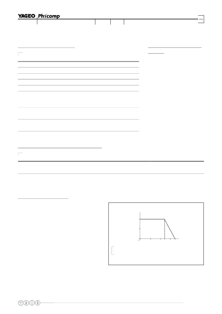
�handbook,� halfpage�
�P�
�(%P� rated� )�
�100�
�50�
�MLB206_1�
�Tamb� (� C)�
�V=� √� (P� X� R)�
�or� max.� working� voltage� whichever� is� less�
�0�
�55�
�0�
�50�
�70�
�100� 125�
�o�
�Where�
�V=Continuous� rated� DC� or�
�AC� (rms)� working� voltage� (V)�
�Fig.� 6� Maximum� dissipation� (P)� in� percentage� of� rated� power� as� a�
�function� of� the� operating� ambient� temperature� (T� amb� )�
�P=Rated� power� (W)�
�R=Resistance� value� (� X� )�
�www.yageo.com�
�Oct� 20,� 2011� V.3�
�发布紧急采购,3分钟左右您将得到回复。
相关PDF资料
YC124-JR-07120KL
RES ARRAY 120K OHM 4 RES 0804
YC248-JR-0710RL
RES ARRAY 10 OHM 8 RES 1506
YC324-JK-072K2L
RES ARRAY 2.2K OHM 4 RES 2012
YE-2RB-A2
SWITCH PLUNGER SPST 25A SCREW
YE-2RV198-A41
SWITCH STRGHT LVR SPST 25A SCREW
YRM33F2BBBNN
SWITCH ROCKER DPDT 20A 125V
YZ-2R-A21
SWITCH PLUNGER SPST 15A SCREW
YZ-2R-A2
SWITCH PLUNGER SPST 15A SCREW
相关代理商/技术参数
YC122-JR-07180KL
功能描述:RES ARRAY 180K OHM 2 RES 0404 RoHS:是 类别:电阻器 >> 网络、阵列 系列:YC122 产品变化通告:Global Part Number Change 9/Aug/2010 标准包装:10,000 系列:RAVF 电路类型:隔离 电阻(欧姆):7.6k 电阻数:4 引脚数:8 每个元件的功率:62.5mW 容差:±5% 温度系数:±200ppm/°C 应用:- 安装类型:表面贴装 封装/外壳:0804(2010 公制),凸起 供应商设备封装:- 尺寸/尺寸:0.079" L x 0.039" W(2.00mm x 1.00mm) 高度:0.014"(0.35mm) 包装:带卷 (TR) 工作温度:-
YC122-JR-07180RL
功能描述:RES ARRAY 180 OHM 2 RES 0404 RoHS:是 类别:电阻器 >> 网络、阵列 系列:YC122 产品变化通告:Global Part Number Change 9/Aug/2010 标准包装:10,000 系列:RAVF 电路类型:隔离 电阻(欧姆):7.6k 电阻数:4 引脚数:8 每个元件的功率:62.5mW 容差:±5% 温度系数:±200ppm/°C 应用:- 安装类型:表面贴装 封装/外壳:0804(2010 公制),凸起 供应商设备封装:- 尺寸/尺寸:0.079" L x 0.039" W(2.00mm x 1.00mm) 高度:0.014"(0.35mm) 包装:带卷 (TR) 工作温度:-
YC122-JR-0718KL
功能描述:RES ARRAY 18K OHM 2 RES 0404 RoHS:是 类别:电阻器 >> 网络、阵列 系列:YC122 产品变化通告:Global Part Number Change 9/Aug/2010 标准包装:10,000 系列:RAVF 电路类型:隔离 电阻(欧姆):7.6k 电阻数:4 引脚数:8 每个元件的功率:62.5mW 容差:±5% 温度系数:±200ppm/°C 应用:- 安装类型:表面贴装 封装/外壳:0804(2010 公制),凸起 供应商设备封装:- 尺寸/尺寸:0.079" L x 0.039" W(2.00mm x 1.00mm) 高度:0.014"(0.35mm) 包装:带卷 (TR) 工作温度:-
YC122-JR-0718RL
功能描述:RES ARRAY 18 OHM 2 RES 0404 RoHS:是 类别:电阻器 >> 网络、阵列 系列:YC122 产品变化通告:Global Part Number Change 9/Aug/2010 标准包装:10,000 系列:RAVF 电路类型:隔离 电阻(欧姆):7.6k 电阻数:4 引脚数:8 每个元件的功率:62.5mW 容差:±5% 温度系数:±200ppm/°C 应用:- 安装类型:表面贴装 封装/外壳:0804(2010 公制),凸起 供应商设备封装:- 尺寸/尺寸:0.079" L x 0.039" W(2.00mm x 1.00mm) 高度:0.014"(0.35mm) 包装:带卷 (TR) 工作温度:-
YC122-JR-071K2L
功能描述:RES ARRAY 1.2K OHM 2 RES 0404 RoHS:是 类别:电阻器 >> 网络、阵列 系列:YC122 产品变化通告:Global Part Number Change 9/Aug/2010 标准包装:10,000 系列:RAVF 电路类型:隔离 电阻(欧姆):7.6k 电阻数:4 引脚数:8 每个元件的功率:62.5mW 容差:±5% 温度系数:±200ppm/°C 应用:- 安装类型:表面贴装 封装/外壳:0804(2010 公制),凸起 供应商设备封装:- 尺寸/尺寸:0.079" L x 0.039" W(2.00mm x 1.00mm) 高度:0.014"(0.35mm) 包装:带卷 (TR) 工作温度:-
YC122-JR-071K5L
功能描述:RES ARRAY 1.5K OHM 2 RES 0404 RoHS:是 类别:电阻器 >> 网络、阵列 系列:YC122 产品变化通告:Global Part Number Change 9/Aug/2010 标准包装:10,000 系列:RAVF 电路类型:隔离 电阻(欧姆):7.6k 电阻数:4 引脚数:8 每个元件的功率:62.5mW 容差:±5% 温度系数:±200ppm/°C 应用:- 安装类型:表面贴装 封装/外壳:0804(2010 公制),凸起 供应商设备封装:- 尺寸/尺寸:0.079" L x 0.039" W(2.00mm x 1.00mm) 高度:0.014"(0.35mm) 包装:带卷 (TR) 工作温度:-
YC122-JR-071K8L
功能描述:RES ARRAY 1.8K OHM 2 RES 0404 RoHS:是 类别:电阻器 >> 网络、阵列 系列:YC122 产品变化通告:Global Part Number Change 9/Aug/2010 标准包装:10,000 系列:RAVF 电路类型:隔离 电阻(欧姆):7.6k 电阻数:4 引脚数:8 每个元件的功率:62.5mW 容差:±5% 温度系数:±200ppm/°C 应用:- 安装类型:表面贴装 封装/外壳:0804(2010 公制),凸起 供应商设备封装:- 尺寸/尺寸:0.079" L x 0.039" W(2.00mm x 1.00mm) 高度:0.014"(0.35mm) 包装:带卷 (TR) 工作温度:-
YC122-JR-071KL
功能描述:RES ARRAY 1K OHM 2 RES 0404 RoHS:是 类别:电阻器 >> 网络、阵列 系列:YC122 产品变化通告:Global Part Number Change 9/Aug/2010 标准包装:10,000 系列:RAVF 电路类型:隔离 电阻(欧姆):7.6k 电阻数:4 引脚数:8 每个元件的功率:62.5mW 容差:±5% 温度系数:±200ppm/°C 应用:- 安装类型:表面贴装 封装/外壳:0804(2010 公制),凸起 供应商设备封装:- 尺寸/尺寸:0.079" L x 0.039" W(2.00mm x 1.00mm) 高度:0.014"(0.35mm) 包装:带卷 (TR) 工作温度:-